Strictly computers, and mainly software, especially system software and networking.
I've just soldered up an adapter for a headset to fit a 2.5mm phone socket and it's the poorest solder job I've ever seen, deeply embarrassing! Still, it worked so that's some kind of success! Think I need a better soldering iron than the 30 year old crap I found in the garage!
I would be interested in the photos though, just out of curiosity. From what you said it sounds like they use normal magnets (not electromagnets) and just move them to intersect more of the disk or less.
Geoff
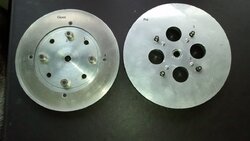
The first picture below is of the classic and pro flywheel.
Item 1. is the four magnets that provide the flywheel speed. The classic magnets mount in plastic tubes connected to the flywheel fan but I broke one so I had to screw some small magnets on myself.
Item 2. are the small magnets I screwed on in place of what should stick through the holes as with the Pro.
Item 3 are the securing screws for the conductve disc that is the brake. The disc on the Classic is held closer to the circumferance and as a result is less likely to come away from the flywheel
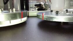
The fourth picture are the flywheels side on and you can see how much thicker the Classic flywheel on the left is.
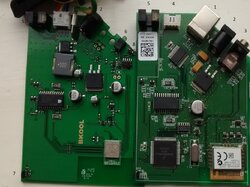
The second picture are the Classic and Pro PCB's side by side:
1. USB B Port for FW loading
2. DC Power In
3. No a clue and have never used it but looks a bit like and aerial socket
4. Socket for the stepper motor
5. Photocell gate for null position of the Magnet Carrier
6. Power inidicator light and probaly has some form of fault indication as well
7. Flywheel speed pickup
8. I assume this is the ANT+ Antenna
The rest is electrickery
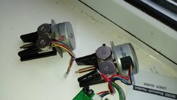
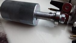
The third picture is the Classic and Pro Stepper Motor and Magnet Carrier.
The motor turns the threaded brass drive screw which moves the magnets in and out of the path of the flywheel conductive disc.
More magnet presented = more braking, Higher Flywheel speed = more braking.
You can just see the tab on the far side of the closest magnet carrier that motors back into the photocell gate which stops the stepper motor whilst nulling the magnet start position. I assume all braking is calculated by the number of rotations of the stepper motor drive from this null position.
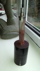
Images 5 and 6 are the Pro and Classic rollers. The Pro Roller keys onto the shaft whereas the Classic shaft is splined all be it due to the picture image you cannot see then to well

")